 by Sam Brown
Geometric dimensioning and tolerancing (GD&T) helps eliminate confusion by providing a shared engineering language. It clearly defines how parts should look, fit and function across every stage of production. If you're involved in designing, machining or inspecting parts, understanding GD&T is crucial.
This guide walks you through the fundamentals of geometric tolerancing, key symbols, real-world applications and how to use it in your process. Whether you're a design engineer or a production manager, you'll find practical insights here. You'll also discover how GD&T supports precision, reduces waste and improves team communication.
Need support from expert machinists?
What is GD&T?
GD&T, sometimes referred to as GTOL, is a standardised symbolic language used to define and communicate part geometry. It describes shapes, positions and acceptable variation in a way that's clear for engineers, machinists and inspectors. You’ll see it used in both 2D technical drawings and embedded directly into 3D CAD models.
Instead of long notes or detailed explanations, GD&T uses simple, compact symbols. These GTOL symbols show the exact form and function of each feature on a part. That leads to fewer mistakes, faster decisions and smoother workflows across your team.
Using GD&T also helps avoid miscommunication between teams during design, machining and inspection. When everyone works from the same clear set of symbols, there’s less room for error. That makes it easier to deliver accurate, consistent results without delays or rework.
Benefits of Implementing GD&T
Implementing geometric dimensioning and tolerancing brings real, measurable advantages to your workflow. It improves communication between teams and reduces rework, inspection time and misunderstandings. This is especially valuable when parts are complex or demand high precision. Here’s how GD&T can benefit your process:
- Speeds up manufacturing by defining only what's critical
- Reduces scrap and rework due to clearer instructions
- Improves inspection accuracy with standardised measurements
- Supports better collaboration between designers and machinists
GD&T also helps you avoid over-tolerancing, a common issue where dimensions are tighter than needed. Overly tight tolerances increase costs and slow down machining unnecessarily. By applying only what's functionally required, GD&T keeps production efficient and cost-effective.
Key GD&T Symbols and Their Meanings
Geometric dimensioning and tolerancing uses a structured set of GTOL symbols to communicate how each part should look and behave. Each symbol belongs to a specific category based on the type of geometric control it provides. Understanding these categories helps you apply geometric tolerancing where it matters most.
| Categories | Characteristics | Symbol |
|---|---|---|
| Form | Straightness | — |
| Flatness |  |
|
| Circularity | ○ | |
| Cylindricity | ⌭ | |
| Orientation | Angularity | ∠ |
| Perpendicularity | ⊥ | |
| Parallelism | // | |
| Location | Position |  |
| Profile | Profile of a Surface | ⌒ |
| Profile of a Line | ⌓ | |
| Runout | Circular Runout | ↗ |
| Total Runout |  |
Form Tolerances
Form tolerances control the shape of a single part feature without referencing any other features. These include straightness, flatness, circularity and cylindricity. Each one helps ensure a part holds its intended shape in real-world conditions.
A shaft might be the right size but still slightly bent or twisted. Straightness tolerance makes sure it stays aligned for smooth operation. This is especially important in rotating or sliding parts where friction must be minimised.
Flatness ensures that a surface lies between two perfectly parallel planes. This is vital when parts must sit flush against each other for proper function. Flatness prevents issues like gaps, leaks or uneven wear over time.
Profile Tolerances
Profile tolerances control the outline or surface contour of a part in 2D or 3D. They’re often used on parts with curves or complex shapes that can’t be defined with simple dimensions. These are common in aerospace, medical and custom-engineered parts.
Profile of a line is applied to cross-sections along a feature's length. Profile of a surface controls the full 3D form of the part's surface. Both ensure the geometry stays within a defined geo tolerance range.
These controls maintain performance and consistency in parts like airfoils, surgical components or housing shells. They help avoid unwanted shape changes during machining or finishing. That keeps the part safe, functional and easy to assemble.
Orientation Tolerances
Orientation tolerances control the tilt or angular alignment of a feature relative to a datum. These include parallelism, perpendicularity and angularity. Each one ensures that part features maintain the correct direction without drifting.
Parallelism keeps surfaces or axes evenly spaced from a reference. Perpendicularity ensures one feature stays at a true 90-degree angle to another. Angularity defines any angle other than 90 degrees between two features.
These tolerances are essential for assemblies with tight alignment requirements. Without them, parts may not seat properly or could interfere during operation. Orientation controls help avoid costly misalignments and part failures.
Location Tolerances
Location tolerances define where features should be placed relative to a datum. These are critical when part features must line up or fit together with other components. They help avoid functional failures and reduce variation in assembly.
Position, concentricity and symmetry are the most common types of location controls. Position tolerance is especially important for fasteners, slots or holes. It ensures those features are placed accurately without over-constraining them.
Concentricity makes sure circular features share a common central axis. Symmetry keeps features balanced around a central plane or axis. These geometric tolerancing methods are vital in rotating components and cosmetic finishes.
Runout Tolerances
Runout tolerances manage how a part behaves while rotating around an axis. These are especially important in shafts, gears or any part that spins during use. They prevent issues like wobbling, vibration and premature wear.
Circular runout controls variation at single cross-sections along the part. Total runout manages surface variation along the full length of rotation. Both help verify the part performs smoothly across its full operational range.
In high-speed machines, even tiny runout variations can lead to failure. Misalignment can damage bearings, shorten tool life or affect final product quality. Geometric dimensioning and tolerancing lets you apply the right geometric tolerance to avoid these problems early on.

Understanding Datum and Datum Reference Frames
Datums are the foundation of geometric tolerancing. They are specific points, planes or axes used as references when measuring features. Without them, geometric tolerance zones would have no reliable place to begin.
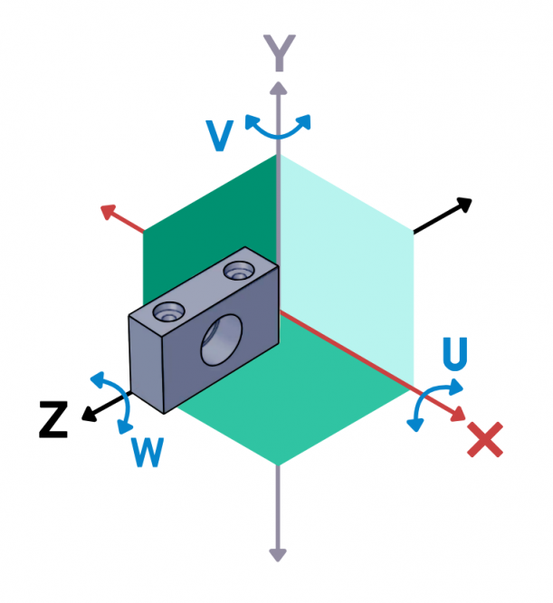
A datum reference frame consists of three elements: primary, secondary and tertiary datums. Together, they form a 3D coordinate system for locating and orienting part features. This makes inspection methods consistent, repeatable and easier to standardise.
For example, the flat bottom of a part might serve as your primary datum. You could then use one side edge as the secondary and a hole centre as the tertiary. This approach simplifies both measurement and assembly during production.
GD&T Rules and Concepts
There are a few key rules that make GD&T such a reliable system for part definition and inspection. One of the most important is the Principle of Independency. This rule means that geometric tolerance and size tolerance are treated separately.
A part can meet its size limits but still fail if it doesn’t meet the geo tolerance. That’s why both need to be specified on critical features. It helps avoid incorrect approvals and ensures higher part quality. You’ll also come across these important concepts often:
- Maximum Material Condition (MMC)
- Least Material Condition (LMC)
- Bonus Tolerance
These rules give more flexibility when a feature shifts away from its maximum or minimum material condition. They support part interchangeability and reduce the chance of costly rejects. When used correctly, they help balance precision and efficiency.
Practical Applications of GD&T
GD&T plays a vital role in industries where accuracy isn’t just preferred—it’s essential. Sectors like aerospace, defence and medical manufacturing depend on exact part fits and flawless functionality. Even minor deviations can lead to costly failures or safety concerns, here are real examples of where GD&T matters:
- Ensuring surgical instruments align with locking mechanisms
- Making aircraft panels fit flush for aerodynamic efficiency
- Aligning connectors in electronics without short circuits
At Penta Precision, we apply geometric tolerancing at every stage of our CNC machining processes. We also offer Machining drawing services to help engineers create clear, inspection-ready documentation. This reduces ambiguity, streamlines production and improves overall quality.
Common Challenges and Misconceptions
Many people assume that GD&T is too complicated or only useful for advanced projects. In reality, it simplifies communication between design, machining and inspection teams. It also helps reduce misunderstandings, rework and production delays.
Common challenges include unclear datums, incorrect GTOL symbols and over-tolerancing parts. These issues often come from inconsistent training or applying standards incorrectly. Fixing them early can lead to faster, more reliable production runs.
Another common misconception is that tighter tolerances always mean higher quality. In truth, they can increase machining time, inspection complexity and cost without real benefit. GD&T allows you to apply precision only where it truly matters.
Implementing GD&T in Your Organisation
Start by training your design, manufacturing and QA teams on GD&T basics. Everyone involved in part creation and inspection should understand how to apply and interpret geometric tolerancing. This creates consistency and avoids time-consuming back-and-forth during production.
Use 3D CAD software that supports semantic GD&T callouts. Follow recognised standards like ISO GPS or ASME Y14.5 to ensure compatibility. This helps your designs move smoothly from concept to machining and inspection.
At Penta Precision, we’ve helped many clients improve results through better use of GD&T. Our team works closely with customers from early design to final inspection. We apply Precision CNC milling techniques to meet tight geometric tolerance requirements with confidence.

Key Takeaways for Using GD&T Effectively
Using geometric dimensioning and tolerancing effectively comes down to clarity, consistency and purpose. It's not about adding more symbols, it's about using the right ones in the right places. These key points will help you get the most out of your drawings:
- Always define datums clearly to avoid inspection ambiguity
- Use tolerance symbol data only where it supports part function
- Combine size and geometric tolerances for total control
GD&T helps prevent miscommunication across design, machining and inspection. It brings clarity to your drawings and ensures parts function as intended. With consistent use, it enhances quality, reduces waste and improves efficiency at every stage.